Being stuck in the house “social distancing” (OMG I’m so bored) has some advantages, one of which is being able to get caught up on a lot of stuff. One of those things is the MFJ-8100K world band shortwave radio kit. That’s the little beastie you see in the photo below that I (ahem) stole borrowed from somewhere on the internet.

Damn, that’s pretty slick looking. It beats the heck out of what the average electronics kit looks like when it’s done. Most of them don’t even offer any kind of decent case. Whether it actually will look like this when it’s done remains to be seen because I haven’t actually built it yet as I write this. Instead of putting it together and taking some photos and talking about it after it’s all done, I’m going to do this live, so to speak, writing and photographing as I go along so you too can experience the joys and pains associated with putting something like this together.
I should warn you ahead of time that this could get pretty lengthy because I’ve done little more than just open the box and it is already looking like this is going to be a problem.
But let’s look at the basics a little more closely before we get started. It’s a world band shortwave receiver with 5 bands. They cover 3.5 – 4.3 mHz, 5.85 – 7.4 mHz, 9.5 – 12.00 mHz, 13.2 – 16.4 mHz and 17.5 – 22 mHz.
As for the basic design, this is a regenerative receiver, a design that dates back to, oh, the 1920s or so, and was quickly abandoned as soon as superhets were developed. And for good reason, as anyone who has ever fallen off their chair from the blast of noise if you tweak the regen just a tad too far and it goes into oscillation can tell you. About the only good thing regenerative receivers have going for them is a fairly low parts count and easy assembly. Well, that’s not really true. They can be decent receivers once you get used to their quirks, but with really high quality superheterodyne designs out there, why even bother with one of these? How did I even end up having this on the shelf in the first place? I don’t remember buying it. Do I have people breaking into the house and leaving me stuff instead of stealing it now?
The first thing I started wondering was why the heck is this thing so expensive?It’s going for $90, for heaven’s sake. And there is nothing exotic or hard to find in the electronics. While that variable capacitor is kind of pricey (that goes for about $20+ alone and I know that because I had to buy one of the things a few months ago) But other than that I think there’s maybe $10 worth of parts in the thing. I suspect that really fancy faceplate and heavy duty metal case probably costs more than the electronics inside does.
But let’s get on with this.
Opening the box and poking around.
This is what the promotional photos tells you is in the box.

First I should point out that this kit starting with the photos below is shown exactly as it came and while I assembled it. The box was still sealed and I hadn’t opened it until I started this. What it really looks like when you open the box is this:
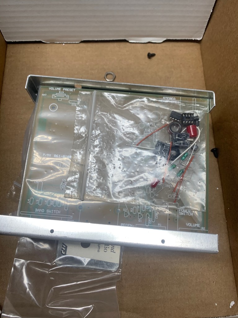
Um, okay… Are those screws and nuts rolling around loose in the box? Yeah, they are. And not just screws and nuts and washers, we got electronic components floating around loose in there too. Oh, goodie.


Opening the box and finding components strewn about all over inside doesn’t exactly inspire confidence about the quality of a product. Whoever originally packed this thing and chucked in the little plastic bags holding the components hadn’t bothered to actually close up the plastic bags.
And as for the case, well, damn, that’s probably the best case I’ve ever seen for a kit in a long time. Beautifully finished, heavy steel, with an equally beautiful brushed polished steel faceplate.

You can’t get much better than that. See what I mean about the case probably costing more than the electronics? It’s – it’s shiny. Oooo
The rest of what was in the box looks like this:

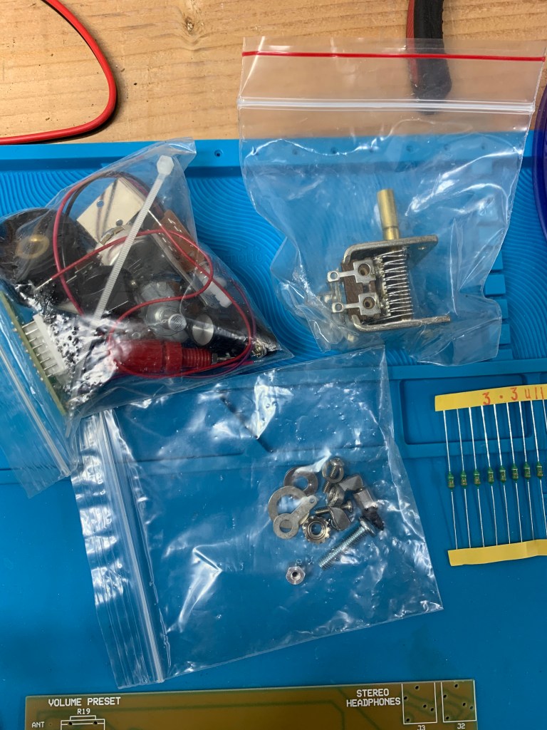
As noted, most of the little baggies containing parts were open and had shed a considerable number of electronic components, screws, washers, etc. all over the inside of the box..
On the far right of the photo above you’ll see a strip of components held together with bits of yellow tape. Those are 3.3 uH inductors and those were not in the kit. I had to dig those out from my “Wall O’ Parts” because the kit wants one, and MFJ either thoughtfully failed to provide one because they figured I’d be getting bored by this time and needed to get up and stretch or something, or it got lost because of they left the baggies open. I expect I shall have to resort to the Wall O’ Parts several times as I try putting this sucker together. I’ve only just started to look at this and sort through parts and I’m already finding stuff missing, so I’m a wee bit irritated. There is nothing more upsetting than getting into an electronics kit and finding parts missing. Me, I have hundreds of components sitting on the shelf (well, if I can find ’em, that is) but the average person building this is not going to have that luxury and is going to be royally ticked off.
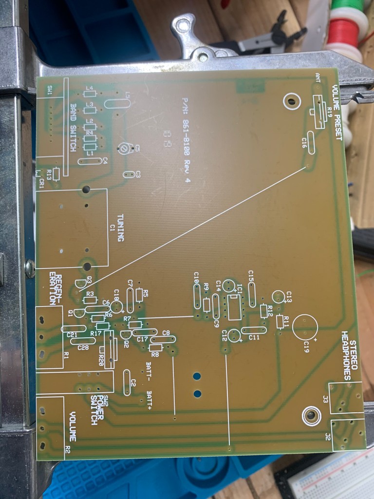
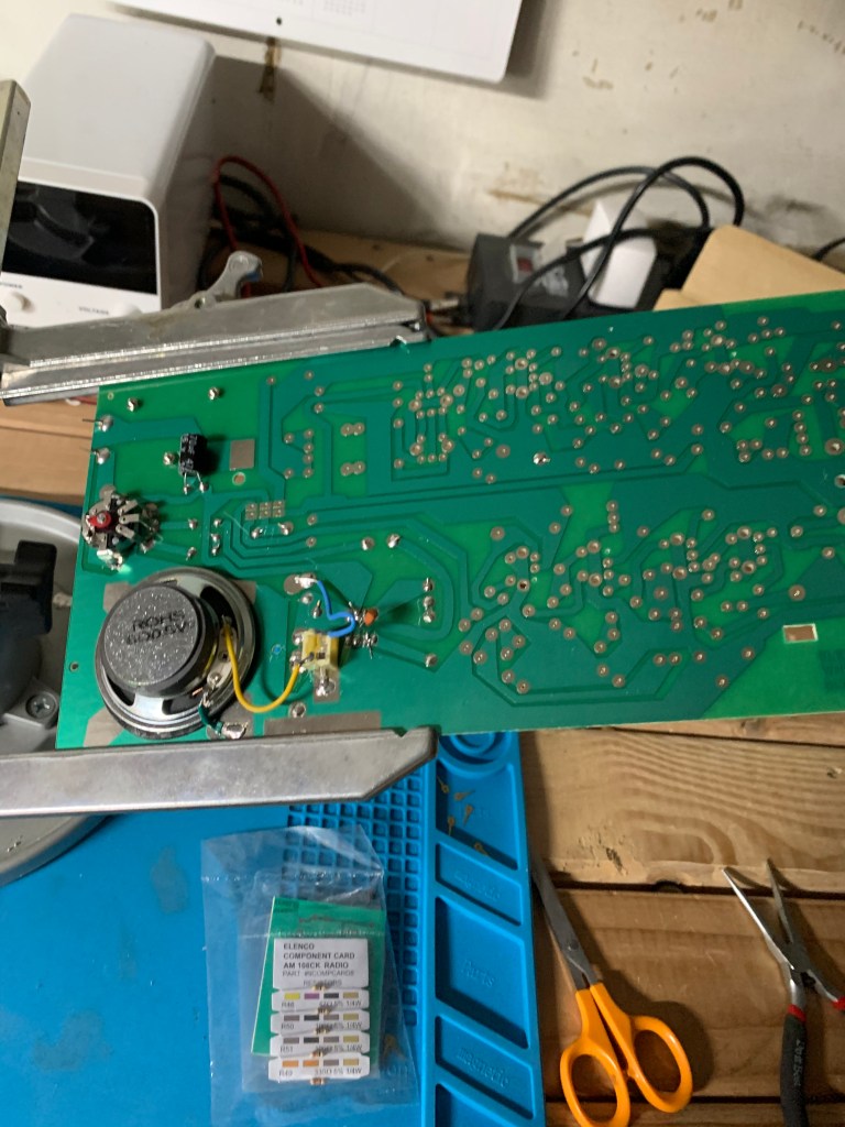
The circuit board looks reasonably well made and the parts locations are all nicely detailed. You could probably put it together without instructions if it weren’t for a few gotchas, like having to wind your own coil on a toroid.
Where’s the fecking Manual???
Now, the more sharp eyed amongst you might have noticed something missing from those photos up there. Where the heck is the manual/assembly instructions? Well, you don’t see it because there isn’t one. Instead of a manual there is a half sheet of paper telling me I need to download the manual from the MFJ website, giving me a URL to go to. So I go to the webpage as instructed and find a bad PDF of the circuit diagram which was so low resolution I couldn’t even make out the symbols or component labels. It looked like someone had almost deliberated fuzzed out all of the labels and component symbols, and the “manual” was actually a booklet in PDF telling me how to use the radio, not how to put it together. No assembly instructions. No readable schematic. Oh, goodie…

A search on MFJ’s site using its own search function turned up a reference leading straight back to the useless info I’d already seen. I finally ran a general search on Google and found the real assembly manual tucked away somewhere on MFJ’s site and I printed it out.
(Update 3/27/20: And now I can’t even find that website, for pete’s sake! I was going to put the link to the correct PDF in here as I edit this before posting it, and when I just tried I get a “page not found” error. MFJ is apparently upgrading its website and I can’t find it at all. Good job, there, MFJ. I didn’t keep a copy of the PDF, but at least I printed the thing out so I can at least take a stab at this. But anyone else wanting that booklet, well, it looks like you’re on your own.)
The manual itself (if you can find it) is actually pretty good. Sort of. Clearly written, mostly, with lots of detail, but sadly lacking in illustrations.
So let’s sling some solder and see what happens.

Now that’s interesting. Look at the 4 inductors up there. Notice anything different about one of ’em? Yeah, the third from the left is about half the physical size of the other three. The big three were supplied with the kit while the small one is my replacement and is about half the physical size, but it is the right specification according to the color codes and I put it on my tester just to double check, and it should be the right one. Is this going to be an issue? No idea at this point. All of the inductors I have in stock are the smaller size.
Also, more missing parts. Just found two resistors are missing. Look at this pic:
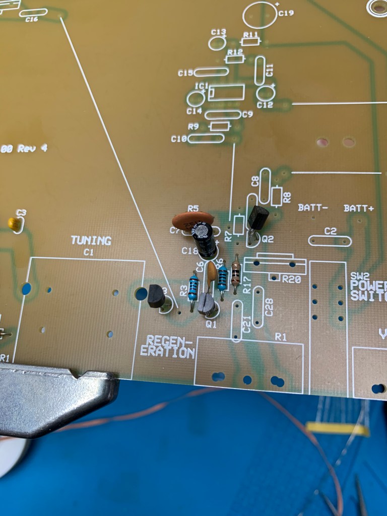
R3 and R6 were missing so I had to pull those off the shelf. Notice that they’re an entirely different color from the kit supplied one, R17. I use the generally more reliable metal film resistors (the blue ones) while the kit supplies carbon resistors (the tan ones). Now very, very rarely the type of resistor can make a difference, so I’m hoping that isn’t the case here.
Later – Missing parts list now sits at 1 missing inductor, 4 missing resistors, and 2 missing capacitors.
And now there’s an issue with one of the electrolytic capacitors.

C14 there next to the IC socket is, according to the instructions, supposed to be a 10 uF cap, but the kit supplies a 1 uF. Or at least I think that’s the one because the 1 uF is the only one left. Do I follow instructions and put in a 10, or use the 1 uF supplied? I finally pulled a 10 uF off the shelf and used that in the hopes that the instructions are right and the parts picker was wrong. (Later – Apparently the 10uF was the right choice because now that it’s done it works)

And speaking of IC sockets, and this applies to whenever you’re soldering a socket, use caution soldering the pins because it is very easy to apply a tiny bit too much solder and end up with solder bridges shorting out the pins. And it’s easy to do a bad joint as well. Double check under a magnifier.
Time to install the variable cap which is how you tune this puppy. And…

And the solder lugs on the cap are way too big for the holes in the circuit board. I could either drill the holes out, which I don’t want to do because the solder pads are none too large to begin with, or I could trim off the lugs. I finally trimmed the lugs off.

Above here I’m trying to mount the volume control and the regen control. They don’t make this easy either. We’ve gone from holes being to small to holes being way, way too big. Note how some of those holes at the top edge of the board have been double drilled, which makes them way too large for the solder lugs on the potentiometers that are supposed to fit in there.
And speaking of soldering, look closely at those solder pads on that board. It’s difficult to see in the photos but almost all of them seem to be covered with some kind of oxidation that makes it difficult for the solder to adhere. I’ve been using a bit of a scotch brite pad held in a needle nose pliers to buff them before I solder anything.

Then there’s the band switch. The switch has 8 pins, the board has 7 holes. Hmm… Let’s look at the manual. Ah, here we are… Oh, nothing. Says nothing about what to do about the missing hole. Oh, goodie.

I ended up bending the extra pin out of the way and keeping my fingers crossed that it wouldn’t get mad at me. (Later – Don’t know if I was supposed to do this or not but the thing is working this way.)
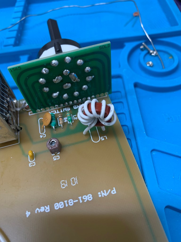
That circle thing with the white wire wound around it is a coil made by winding 8 turns of wire around a provided toroid core. Some people get a bit weird about winding their own coils. I’m not sure why. A small one like this is a piece of cake. They don’t get nasty until you start having to make ’em with, oh, 30 or 40 turns.

And there it is, ready for testing. It runs off 9V and supposedly a 9V battery will last for weeks and weeks as long as you remember to turn it off. I don’t have a 9V battery, tho, so I hooked it up to my DC power supply and…
Damn, I wish my upload speed wasn’t about 15K baud so I could put up a video of this, but the damned thing actually works! I won’t go through all of the alignment procedures because they will bore you to tears. This is, believe it or not, an actual, working SW receiver. Not a very good one, granted, but it will pick up something.
But then there’s this

This is it fully assembled, mostly. You will note that I don’t have the knobs on. There is a reason for that. MFJ neglected to include the collar nuts you need to actually attach the front properly, anchor the controls down so I can put the knobs on. Now there were indeed collar nuts in the box. You probably saw that in the photos from the box opening. But they were for control shafts about twice the size of these. Sigh… Thanks again, MFJ. Complete assembly is going to have to wait until I can get the right sized nuts.
Okay, this has gone on long enough. Let’s wrap this up. What’s the overall assessment of this beastie?
Well, on the plus side it looks good. It is, amazingly enough, a working radio receiver, although not what I’d call a good working radio. It wasn’t hard to put together. Just about anyone who knows which end of a soldering iron to grab could put this together. Well, mostly, with the application of a bit of common sense. And that case sure looks cool.

But then we come to the negative side.
First problem is the price. They’re getting $90 for this thing, my friends. While the Elenco AM/FM receiver I put together a couple of weeks ago is far more sophisticated, much more sensitive, has an actual amplifier so it can drive a speaker and not just headphones, and sells for half the cost of the MFJ kit at about $44. Granted, it doesn’t come with the fancy case, but you can always cobble together something to throw the Elenco into. And when you’re done with the Elenco you’ll have a radio you can actually listen to, whereas the MFJ is never going to be more than a curiosity for most people.
Then there are the missing parts. A half dozen or so resistors, two capacitors, an inductor, the collar nuts to hold the controls in place, all missing. I don’t know if this was a problem with the person who packed up the parts in the first place, or if they were lost somehow because the bags weren’t closed, or what. My guess is that they were never in there to begin with, because while parts did spill out, the box was sealed and there were no openings for anything to fall out.
As I said before missing parts isn’t much of a problem for me, but for someone who doesn’t have a “Wall O’ Parts”, like some kid doing this for a STEM project or someone who just enjoys occasionally tinkering with kits, this could be a real problem. Sure, you could probably email MFJ and they’d probably replace the parts. Eventually. Maybe. But come on, they should have all been in there in the first place.
Then there’s the manual. Or, rather, the lack of one. What’s the matter with you people over at MFJ? You could throw an 100 page product catalog into the box but you couldn’t be bothered to run off a 30 page manual on the office printer and throw that in too? And then even worse, direct me to a website to find the manual that doesn’t exist? Or to utterly useless schematics?
I’m really disappointed with this because this could have been a really good kit if MFJ had bothered to just just be a little more careful.
So, because of the high price, the missing parts, the missing manual, etc. I can’t score the 8100 very high. On a scale of A to F, where A is excellent and F is abysmal, I’d give the 8100 kit a D+.