

Now if you’ve been reading this for a while you know there are two things I really, really like – gardening and fiddling with electronics. And when winter rolls in and shuts down gardening, that leaves electronics to occupy my time. Since I am still waiting for parts for the Great Radio Fiasco Project, I was looking for something else to play with and I ran across this on Amazon-

I like playing around with kits, but I hadn’t built one in ages because there aren’t a lot of them out there any more, and the ones that are on the market seem to either be for things I don’t want or need, or are geared for the kids STEM market and are pretty much useless. This one seemed interesting, though. And it was only fourteen bucks, so if it did turn out to be junk, I wouldn’t be out a lot of money. And it I might get an article out of it for the blog.
Let’s talk about kits in general, first. Once upon a time there was a very good reason why kits came about. Before the advent of things like printed circuit boards and semiconductors and all that stuff we take for granted these days, electronic devices like radios, record players, television sets, etc. were built almost entirely by hand, by workers who strung all of the connecting wires, soldered all of the components, etc. Building even a simple radio receiver required placing, by hand, dozens of individual components and hand soldering dozens, even hundreds of connections. Armies of individual skilled assembly people labored for hours at workstations to put these things together. Labor costs money. A lot of money. And eventually technologies like printed circuit boards and robotic assembly systems largely replaced those armies of workers, resulting in the ultra-cheap electronics we have today.
But back then, with labor such a huge part of the cost, someone came up with the idea of eliminating the labor entirely and just selling the parts and some instructions to people and they could build it themselves. The company still made a few bucks, and the buyer of the kit saved a lot of money by replacing factory labor with his/her own. And there were a lot of people willing to do this. Not just to save money but because a lot of people get a great deal of satisfaction from building things.
But as electronics became more complex with people demanding more and more features, designing and producing kits became increasingly expensive. At the same time because of robotic assembly lines and other advances in technology, it became cheaper and cheaper to produce fully assembled and tested electronics. It got to the point where making a kit was often considerably more expensive than just buying the thing outright. There are still kit makers out there, of course. But most of the kits I see these days are for cheap and pretty much useless little gadgets that you’d build and tinker with for a while, then shove it into a box until your children throw it away after you’re dead.
This looked like it might be interesting, though, and it was only $14 bucks, so what the heck. When you buy these cheap kits these days it’s something of a crapshoot. Reading the reviews can help, but with so many fake reviews, and reviews by, well, idiots, really, not even those are very helpful, I’m afraid. (I could probably do a whole column on just how to try to decipher product reviews on Amazon and other online vendors.)

When it arrived it was about what I expected. Instructions were almost certainly translated from Chinese into English by computer, but unlike a lot that I’ve read, they were actually useful and covered all the important points if you take your time.
Tools
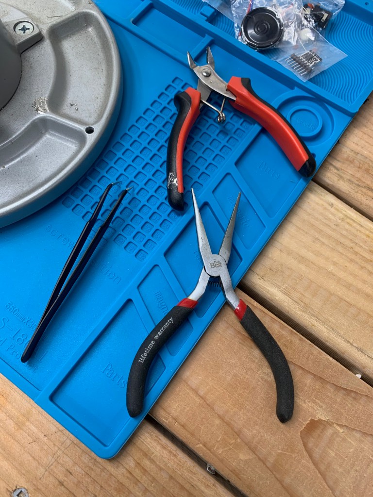
Now before you get started you’re going to need some basic tools. If you’ve ever tinkered with electronics before you almost certainly have everything you need to put this sucker together. You’ll need a needle nose pliers with a fine tip to help place components. A tweezers will help too. Some of the components are pretty small. You’ll also need a wire cutter for snipping off the wires on components after they’ve been soldered onto the circuit board. You’ll need solder, of course, and you’re going to need the smallest diameter solder you can probably get. The solder I used was 0.032″ in diameter, 60/40 rosin core. If you use anything bigger than that you’re going to have a lot of problems with solder flowing places where you don’t want it.
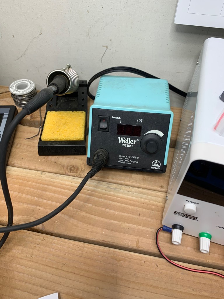
You need a soldering iron, of course. Just about any hobbyist soldering pencil will work if it has a fine enough tip. I have a Weller variable temp soldering iron that I’ve had for years now. I like variable temperature soldering equipment because it lets me adjust the temperature to suit the type of solder I’m using, the size of the components, etc. They’re more expensive than a hobbyist soldering pencil, but not that much more expensive. This one isn’t in production any more, I think, but you can get a variable temp soldering iron for about $100 or less. A lot less if you shop around. Unless you use a soldering iron a lot, don’t spend a lot on one. What’s most important is that it has interchangeable tips so you can change the size of the tip to suit the work you’re doing. With this kit I used a very small spade shaped tip because I was working in rather tight quarters on this kit.
You’re going to need two more things. One is absolutely essential, the other highly recommended but not absolutely necessary.

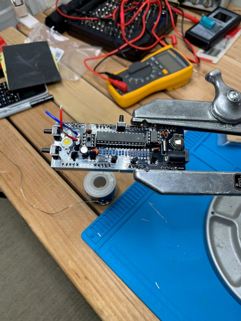
You need something to hold the circuit board while you’re putting everything together. You’re going to be holding your soldering iron in one hand, solder in the other, holding a part in place with your third hand, and holding the circuit board with your fourth hand… Hm? What? You only have two hands? Yeah, so do I, which is why you need something like this. It’s a Panavise circuit board holder and while it isn’t ridiculously expensive, at around $60 – $70, it isn’t exactly pocket change either. I do a lot of work on circuit boards so something like this is absolutely necessary for me. If you’re just slapping a kit together, you can get away with something a lot cheaper or even cobble something together on your own out of alligator clips and stiff wire.
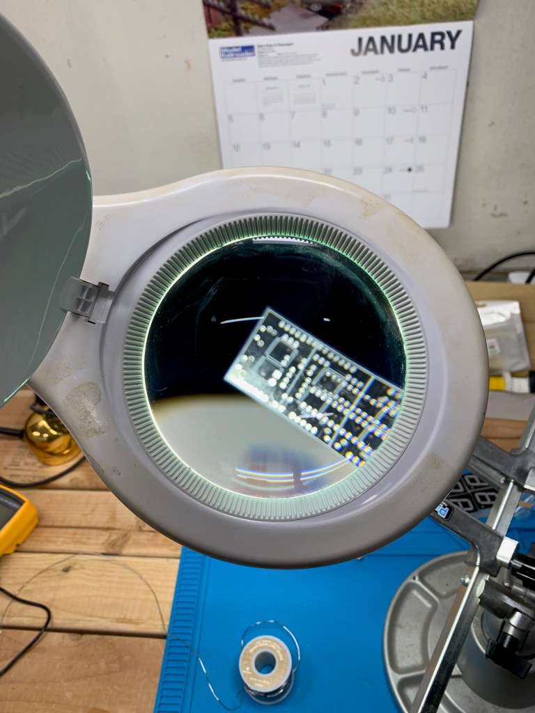
The other item that is very nice to have but not absolutely essential is a light on an articulated arm so you can aim it where you need it, with a built in magnifier. A lot of the components are very small, and a lot of circuit boards are very tightly packed, and even if you have good eyesight it can be a real strain to work on some of this stuff without some kind of magnification and good lighting. A light like this on an articulated arm with a built in magnifier can be had for about, oh, $40 or so.

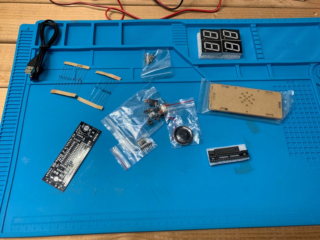
Now, on to the clock itself. Putting it all together isn’t extraordinarily difficult, but it is a bit fiddly. There are a lot of solder joints to make. There’s a 28 pin IC socket, two 8 pin IC sockets, 16 resistors, assorted capacitors, a few transistors, a surface mount LED and several other goodies that all have to be fitted onto that board and soldered.
A few words about soldering: I’m not going to try to teach you soldering here. I’ve heard people claim that soldering is an art. It isn’t. Soldering is basic physics. It is the application of heat to a connector causing the solder and flux to flow and adhere to the connectors to form an electrically conductive connection between two or more components. Anyone can learn to solder, but it takes some knowledge and a lot of practice to do it properly. If you don’t know how to solder, or are just learning, this kit probably isn’t the place to practice. There are a lot of solder joints, spaced very close together, and it’s easy to end up with solder bridges, spatter and other problems. So if you’re new to this I’d recommend you try something more simple. Run a search for “solder training kit” over on Amazon or look at the other electronics suppliers out there and you can find more kits that are designed to teach you how to solder.

Some of the parts in this kit are very tiny and can be difficult to deal with, like soldering headers to a very, very tiny circuit board with an SMD chip on it that has to plug into one of the sockets. And the LED on the board is surface mount. Don’t let that scare you.
I’ve been soldering for, well, probably for longer than a lot of you reading this have been alive, so I zipped through that pretty quickly.
Anyway, the whole kit is very well designed, certainly above average for this kind of thing. The circuit board itself is beautifully made, with outlines and labels printed on the board itself showing the position of the components. All things considered, this is one of the better kits I’ve seen.
There were no missing parts, the instructions were decent, everything was well made. It is definitely a winner all the way around.

Even better, it worked the first time I powered it up! It requires about 5V DC and is intended to run off USB, but I just hooked it up to my variable DC power supply, turned on the power and away it went. It’s a really nice little clock, too. It has a photocell to adjust the brightness of the display depending on ambient conditions, a thermistor that lets it sense the temperature (the display cycles between time and temperature), has an alarm and it talks! Well, I’m not sure about the talking part because I haven’t hooked the speaker up yet. It comes with a clear plastic case that I haven’t put together yet. Eventually I’ll probably put together a power supply for it because I don’t want to have to run it off a computer’s USB port. I should have a 5V wallwart kicking around that would do the job.
Disclaimer: I do not get paid for reviewing products. I do not get special deals, free equipment, components or anything else. All the tools, equipment, parts, and everything you see here or I write about were purchased by me at full retail prices.

I knew nothing about soldering till I read this! Quite the read!!! Thanks
LikeLike
I always hope articles like this are helpful. Response to articles about amateur radio and electronics always seem to attract more readers than anything else I write about here. That surprised me. I assumed people would find this dull.
LikeLiked by 1 person